Module
LGAD Sensors
LGAD sensors are the heart of ETL. Reverse bias above -200V is needed for the internal gain and good time resolution.
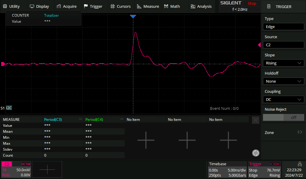
Module v0b allows to wire bond one pixel of a 2x2 pixel sensor to an analog amplifier.
This channel can be read out with a scope through the SMA connector, and a signal from a beta source or cosmic (needs patience) will look like the image below.

ETROC Chip
Overview
Geometry and Addressing
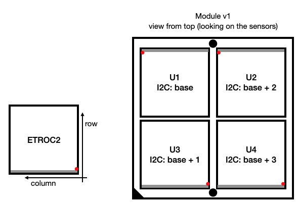
Geometry and numbering scheme of the pixels:

Geometry and numbering scheme of ETROCs with addressing:

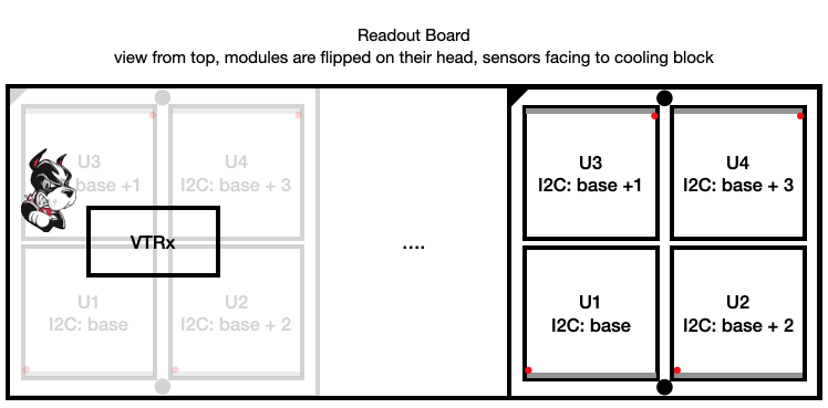
The base address of each module is automatically set through appropriate connections on the RB. It starts at 0x60 and is incremented by 4 for each module, where module counting starts with the module below the VTRX+.
Configuration
The default configuration sets every ETROC into dual port mode (readout through 2 elinks, one per lpGBT).
elinks and link inversions
Differential pairs can be swapped, but the resulting signal can be inverted inside the lpGBTs. Inversion of clocks usually has no effect, but an inverted elink will not lock. Inversions are defined in the corresponding configuration files, and are specific both for the RB and module version.
Obtaining noise thresholds
We have 3 ways of determining the noise thresholds:
-
Automatic (internal) calibration: Implemented as
etroc.auto_threshold_scan(row=row, col=col, broadcast=False, offset=offset)for each pixel, this scan will return the baseline and a determined noise width. If a number is specified for offset, this offset will be used instead of the noise width. Ifoffset='auto', the noise width will be used to set the threshold to baseline + noise width. Using a fixed offset of 10-15 for a reasonable noisy pixel is the preferred method to configure the ETROC for data taking. -
Internal threshold scan The accumulator register of each pixel can be used to manually obtain S-curves.
-
External threshold scan, relying on data readout